Techniques
All applicable parameters for each technique can be found here.
For the inheritance hierarchy of the the techniques, see PalmSens.Core.
See section ‘Available techniques’ in the PSTrace manual for more information about the techniques.
Each technique is identified by a specific integer value. This integer value can be used to create a class derived from the corresponding technique, as follows:
PalmSens.Method.FromTechniqueNumber(integervalue)Alternatively, you can use the method id:
PalmSens.Method.FromMethodID(stringvalue)Both values are indicated in this reference for each technique.
The techniques are also directly available from the PalmSens.Techniques namespace.
Please refer to the PSTrace manual for explanations and expected values for each parameter.
Common properties
| Property | Description | Type |
|---|---|---|
|
The technique number used in the firmware |
|
|
Some user notes for use with this method |
|
|
Standby Potential (for use with cell on after measurement) |
|
|
Standby time (for use with cell on after measurement) |
|
|
Enable/disable cell after measurement |
|
|
Determines the minimum peak height in µA. Peaks lower than this value are neglected. |
|
|
The minimum peak width, in the unit of the curves X axis. Peaks narrower than this value are neglected. |
|
|
The smoothlevel to be used. |
|
|
Ranging information, settings defining the minimum/maximum/starting current range |
|
|
Adjusts sampling on instrument to account for mains frequency. It accepts two values: 50 for 50Hz 60 for 60Hz |
|
|
Mains frequency
To eliminate noise induced by other electrical appliances it is highly recommended to set your regional mains frequency (50/60 Hz) in the static property |
Pretreatment settings
The following properties specify the measurements pretreatment settings:
| Property | Description | Type |
|---|---|---|
|
Conditioning potential in Volt |
|
|
Conditioning duration in seconds |
|
|
Deposition potential in volt |
|
|
Deposition duration in seconds |
|
|
Equilibration duration in seconds. |
|
Linear Sweep Voltammetry
-
Short name: LSV
-
Class:
Palmsens.Techniques.LinearSweep -
TechniqueID: 0 -
MethodID:"lsv"
| Property | Description | Type |
|---|---|---|
|
Potential where scan starts. |
|
|
Potential where measurement stops. |
|
|
Step potential |
|
|
The applied scan rate. The applicable range depends on the value of E step since the data acquisition rate is limited by the connected instrument. |
|
Differential Pulse Voltammetry
-
Short name: DPV
-
Class:
Palmsens.Techniques.DifferentialPulse -
TechniqueID: 1 -
MethodID:"dpv"
| Property | Description | Type |
|---|---|---|
|
Potential where scan starts. |
|
|
Potential where measurement stops. |
|
|
Step potential |
|
|
The applied scan rate. The applicable range depends on the value of E step since the data acquisition rate is limited by the connected instrument. |
|
|
Pulse potential |
|
|
The pulse time |
|
Square Wave Voltammetry
-
Short name: SWV
-
Class:
Palmsens.Techniques.SquareWave -
TechniqueID: 2 -
MethodID:"swv"
| Property | Description | Type |
|---|---|---|
|
Potential where scan starts. |
|
|
Potential where measurement stops. |
|
|
Step potential |
|
|
Amplitude of square wave pulse. Values are half peak-to-peak. |
|
|
The frequency of the square wave |
|
Normal Pulse Voltammetry
-
Short name: NPV
-
Class:
Palmsens.Techniques.NormalPulse -
TechniqueID: 3 -
MethodID:"npv"
| Property | Description | Type |
|---|---|---|
|
Potential where scan starts. |
|
|
Potential where measurement stops. |
|
|
Step potential |
|
|
The applied scan rate. The applicable range depends on the value of E step since the data acquisition rate is limited by the connected instrument. |
|
|
The pulse time |
|
AC Voltammetry
-
Short name: ACV
-
Class:
Palmsens.Techniques.ACVoltammetry -
TechniqueID: 4 -
MethodID:"acv"
| Property | Description | Type |
|---|---|---|
|
Potential where scan starts. |
|
|
Potential where measurement stops. |
|
|
Step potential |
|
|
Amplitude of sine wave. Values are RMS |
|
|
The frequency of the AC signal |
|
Cyclic Voltammetry
-
Short name: CV
-
Class:
Palmsens.Techniques.CyclicVoltammetry -
TechniqueID: 5 -
MethodID:"cv"
| Property | Description | Type |
|---|---|---|
|
Potential where scan starts and stops. |
|
|
First potential where direction reverses. |
|
|
Second potential where direction reverses. |
|
|
Step potential |
|
|
The applied scan rate. The applicable range depends on the value of E step since the data acquisition rate is limited by the connected instrument. |
|
|
The number of repetitions for this scan |
|
Fast Cyclic Voltammetry
-
Short name: FCV
-
Class:
Palmsens.Techniques.FastCyclicVoltammetry -
TechniqueID: n/a -
MethodID:"fcv"
Outdated class. PalmSens 3 and 4 only. For CV’s with sampling over 5000 data points per second, use the regular Cyclic Voltammetry constructor instead.
Chronopotentiometric Stripping
-
Short name: SCP
-
Class:
PalmSens.Techniques.ChronoPotStripping -
TechniqueID: 6 -
MethodID:"scp"
| Property | Description | Type |
|---|---|---|
|
Potential where measurement stops. |
|
|
The maximum measurement time. This value should always exceed the required measurement time. It only limits the time of the measurement. When the potential response is erroneously and E end is not found within this time, the measurement is aborted. |
|
|
The applied current range |
|
|
If specified as 0, the method is called chemical stripping otherwise it is constant current stripping. The current is expressed in the applied current range. |
|
Chronoamperometry
-
Short name: CA
-
Class:
PalmSens.Techniques.AmperometricDetection -
TechniqueID: 7 -
MethodID:"ca"
| Property | Description | Type |
|---|---|---|
|
Potential during measurement. |
|
|
Time between two current samples. |
|
|
Total run time of scan. |
|
Pulsed Amperometric Detection
-
Short name: PAD
-
Class:
PalmSens.Techniques.PulsedAmpDetection -
TechniqueID: 8 -
MethodID:"pad"
| Property | Description | Type |
|---|---|---|
|
The dc or base potential. |
|
|
Potential in pulse. Note that this value is not relative to dc/base potential, given above. |
|
|
The pulse time. |
|
|
DC: I(dc) measurement is performed at potential E, pulse: I(pulse) measurement is performed at potential E pulse, differential: I(dif) measurement is I(pulse) - I(dc) |
|
|
Time between two current samples. |
|
|
Total run time of scan. |
|
Fast Amperometry
-
Short name: FAM
-
Class:
PalmSens.Techniques.FastAmperometry -
TechniqueID: 9 -
MethodID:"fam"
| Property | Description | Type |
|---|---|---|
|
Equilibration potential at which the measurement starts |
|
|
Potential during measurement |
|
|
Time between two current samples |
|
|
Total run time of scan |
|
Chronopotentiometry
-
Short name: CP
-
Class:
PalmSens.Techniques.Potentiometry -
TechniqueID: 10 -
MethodID:"cp"
| Property | Description | Type |
|---|---|---|
|
The current to apply. The unit of the value is the applied current range. So if 10 uA is the applied current range and 1.5 is given as value, the applied current will be 15 uA. |
|
|
The applied current range. |
|
|
Total run time of scan. |
|
|
Time between two potential samples. |
|
Open Circuit Potentiometry
-
Short name: OCP
-
Class:
PalmSens.Techniques.OpenCircuitPotentiometry -
TechniqueID: n/a -
MethodID:"ocp"
The same as Chronopotentiometry as setting the Current to 0.
| Property | Description | Type |
|---|---|---|
|
Total run time of scan. |
|
|
Time between two potential samples. |
|
Multiple Pulse Amperometry
-
Short name: MPAD
-
Class:
PalmSens.Techniques.MultiplePulseAmperometry -
TechniqueID: 11 -
MethodID:"mpad"
| Property | Description | Type |
|---|---|---|
|
First potential level in which the current is recorded |
|
|
Second applied potential level |
|
|
Third applied potential level |
|
|
The duration of the first applied potential |
|
|
The duration of the second applied potential |
|
|
The duration of the third applied potential |
|
|
Total run time of scan. |
|
Electrochemical Impedance Spectroscopy
-
Short name: EIS
-
Class:
PalmSens.Techniques.ImpedimetricMethod -
TechniqueID: 14 -
MethodID:"eis"
The most common properties are described first.
These are used for a typical EIS measurement, a scan over a specified range of frequencies.
For example, using the default properties ScanType = ImpedimetricMethod,
enumScanType.FixedPotential and FreqType = ImpedimetricMethod.enumFrequencyType.Scan.
The additional properties used for a TimeScan and a PotentialScan are detailed separately in next sections.
| Property | Description | Type |
|---|---|---|
|
Scan type specifies whether a single or multiple frequency
scans are performed. When set to |
|
|
The DC potential of the applied sine |
|
|
The amplitude of the applied sine in RMS (Root Mean Square) |
|
|
Frequency type specifies whether to perform a scan on a range of frequencies or to measure a single frequency. The latter option can be used in combination with a TimeScan or a Potential Scan. |
|
|
The highest frequency in the scan, also the frequency at which the measurement is started |
|
|
The lowest frequency in the scan |
|
|
The number of frequencies included in the scan |
|
|
Each measurement point of the impedance spectrum is performed during the period specified by SamplingTime. This means that the number of measured sine waves is equal to SamplingTime * frequency. If this value is less than 1 sine wave, the sampling is extended to 1 / frequency. So for a measurement at a frequency, at least one complete sine wave is measured. Reasonable values for the sampling are in the range of 0.1 to 1 s. |
|
|
The impedance measurement requires a stationary state. This means that before the actual measurement starts, the sine wave is applied during MaxEqTime only to reach the stationary state. The maximum number of equilibration sine waves is however 5. The minimum number of equilibration sines is set to 1, but for very low frequencies, this time is limited by MaxEqTime. The maximum time to wait for stationary state is determined by the value of this parameter. A reasonable value might be 5 seconds. In this case this parameter is only relevant when the lowest frequency is less than 1/5 s so 0.2 Hz. |
|
Time Scan
In a Time Scan impedance spectroscopy measurements are repeated for a specific amount of time at a specific interval.
| Property | Description | Type |
|---|---|---|
|
RunTime is not the total time of the measurement, but the time in which a measurement iteration can be started. If a frequency scan takes 18 seconds and is measured at an interval of 19 seconds for a RunTime of 40 seconds three iterations will be performed. |
|
|
IntervalTime specifies the interval at which a measurement iteration sh ould be performed, however if a measurement iteration takes longer than the interval time the next measurement will not be triggered until after it has been completed. |
|
Potential Scan
In a Potential Scan impedance spectroscopy measurements are repeated over a range of DC potential values.
| Property | Description | Type |
|---|---|---|
|
The DC potential of the applied sine wave to start the series of iterative measurements at. |
|
|
The DC potential of the applied sine wave at which the series of iterative measurements ends. |
|
|
The size of DC potential step to iterate with. |
|
Recording extra values (BiPot, Aux, CE Potential…)
The PalmSens.Method.ExtraValueMsk property allows you to record an additional value during your measurement.
Not all techniques support recording extra values, the SupportsAuxInput and SupportsBipot properties are used to indicate whether a technique supports the recording of these values.
The default value for PalmSens.Method.ExtraValueMsk is PalmSens.ExtraValueMask.None.
-
None, no extra value recorded (default)
-
Current
-
Potential
-
WE2, record BiPot readings (The behavior of the second working electrode is defined with the method’s
BipotModePSproperty.EnumPalmSensBipotMode.Constantsets it to a fixed potential andEnumPalmSensBipotMode.Offsetsets it to an offset of the primary working electrode. The value in Volt of the fixed or offset potential is defined with the method’sBiPotPotentialproperty.) -
AuxInput, similar to PSTrace it is possible to configure the readings of the auxiliary input. Using the
PalmSens.AuxInput.AuxiliaryInputclass you can assign a name, offset, gain and unit to the auxilliary input. The following example demonstrates how to set up the Pt1000 temperature sensor from PSTrace.
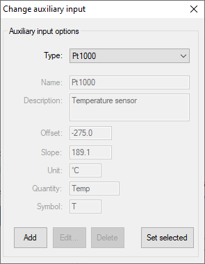
psCommSimple.comm.AuxInputSelected = new PalmSens.AuxInput.AuxiliaryInputType(
    true, "Pt1000", "Temperature sensor", -275f, 189.1f, new PalmSens.Units.Temperature()
);
The can be ignored and set to true, the second argument is the name, third is the description, fourth the offset, fifth the slope and the final argument is an instance of one of the unit classes in the PalmSens.Units namespace.
-
Reverse, record reverse current as used by Square Wave Voltammetry
-
PolyStatWE, not supported in the PalmSens SDK
-
DCcurrent, record the DC current as used with AC Voltammetry
-
CEPotential, PalmSens 4 only
Multiplexer
The PalmSens.Method class is also used to specify the multiplexer settings for sequential and alternating measurements.
Alternating multiplexer measurements restricted to the Chronoamperometry and Chronopotentiometry techniques.
The enumerator property PalmSens.Method.MuxMethod defines the type multiplexer measurement.
// Default setting, no multiplexer
methodCA.MuxMethod = MuxMethod.None;
methodCA.MuxMethod = MuxMethod.Alternatingly;

methodCA.MuxMethod = MuxMethod.Sequentially;

// The channels on which to measure are specified in a boolean array
PalmSens.Method.UseMuxChannel: methodCA.UseMuxChannel = new bool[] {
    true, true, false, false, false, false, false, true
};
The code above will perform a measurement on the first two and last channels of an 8-channel multiplexer. For a 16-channel multiplexer you would also need to assign true or false to the last 8 channels.
Alternating multiplexer measurement can only measure on successive channels and must start with the first channel (i.e. it is possible to alternatingly measure on channels 1 through 4 but it is not possible to alternatingly measure on channel 1, 3 and 5). The multiplexer functionality is demonstrated in the PSSDKMultiplexerExample project.
Multiplexer settings
When using a MUX8-R2 multiplexer the multiplexer settings must be set digitally instead of via the physical switches on the earlier multiplexer models.
The type of multiplexer should be specified in the connected device’s capabilities, when the multiplexer is connected before connecting to the software the capabilities are updated automatically.
Otherwise, when using the MUX8-R2 the PalmSens.Devices.DeviceCapabilities.MuxType should be set to PalmSens.Comm.MuxType.Protocol manually or by calling PalmSens.Comm.CommManager.ClientConnection.ReadMuxInfo, PalmSens.Comm.CommManager.ClientConnection.ReadMuxInfoAsync when connected asynchronously.
For the MUX8-R2 the settings for a measurement are set in PalmSens.Method.MuxSett property with an instance of the PalmSens.Method.MuxSettings class.
For manual control these settings can be set using the PalmSens.Comm.ClientConnection.SetMuxSettings function, PalmSens.Comm.ClientConnection.SetMuxSettingsAsync when connected asynchronously.
method.MuxSett = new Method.MuxSettings(false) {
    CommonCERE = false,
    ConnSEWE = false,
    ConnectCERE = true,
    OCPMode = false,
    SwitchBoxOn = false,
    UnselWE = Method.MuxSettings.UnselWESetting.FLOAT
};
Versus OCP
The versus open circuit potential settings (OCP) are defined in the PalmSens.Method.OCPmode, PalmSens.Method.OCPMaxOCPTime, and PalmSens.Method.OCPStabilityCriterion properties.
The OCPmode is a bitmask specifies which of the following technique dependent properties or combination thereof will be measured versus the OCP potential:
-
-
BeginPotential= 1 -
EndPotential= 2
-
-
-
Vtx1Potential= 1 -
Vtx2Potential= 2 -
BeginPotential= 4
-
-
-
Potential= 1
-
-
Electrochemical Impedance Spectroscopy (fixed potential and time scan)
-
Potential= 1
-
-
Electrochemical Impedance Spectroscopy (potential scan)
-
BeginPotential= 1 -
EndPotential= 2
-
The progress and result of the versus OCP measurement step are reported in the PalmSens.Comm.MeasureVersusOCP class, which can be obtained by subscribing to the PalmSens.Comm.CommManager.DeterminingVersusOCP event which is raised when the versus OCP measurement step is started.
// Defining vs OCP measurement step for CV
// Measure (Vtx1Potential) 1 + (Vtx2Potential) 2 + (BeginPotential) 4 = 7 versus the OCP potential
_methodCV.OCPmode = 7;

// Sets the maximum time the versus OCP step can take to 10 seconds
_methodCV.OCPMaxOCPTime = 10;

// The OCP measurement will stop when the change in potential over time is less than 0.02mV/s,
// when set to 0 the OCP measurement step will always run for the OCPMaxOCPTime
_methodCV.OCPStabilityCriterion = 0.02f;
Properties for EmStat Pico
There are two method parameters specific to the EmStat Pico.
The PalmSens.Method.PGStatMode property sets the mode in which the measurement should be run, low power, high speed or max range.
This mode can be set for all techniques but Electrochemical Impedance Spectroscopy.
The second property is PalmSens.Method.SelectedPotentiostatChannel which let you choose on which channel the EmStat Pico should run the measurement.